
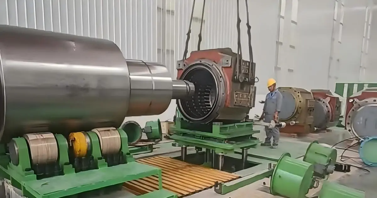
Rolling mill bearing selection requires checking the bearing position, radial and axial loads, operating speed, fits, clearance or setting, and lubrication arrangement. Start by identifying how the roll is supported and which bearing assembly controls axial movement. A radial roll neck bearing, an axial locating bearing and a gearbox bearing perform different functions, even when they operate in the same mill.
For a new arrangement, selection involves load calculations and a review of the roll, chock and surrounding components. For a replacement, begin with the original bearing specification and establish whether the operating conditions or mounting interfaces have changed. Matching the bore, outside diameter and width does not establish interchangeability.
1. Identify the Bearing Position and Load Path
Record the mill type and the bearing’s installation position before comparing bearing types. Work rolls, backup rolls, intermediate rolls and drive shafts can use different arrangements. The assembly drawing should show which bearings support radial forces, which locate the shaft axially and where thermal movement is accommodated.
Roll neck radial support
Roll neck bearings transfer forces from the roll to the chock. Available radial space, roll neck diameter, rolling load, speed and mounting method constrain the selection. Four row cylindrical roller bearings and four row tapered roller bearings are used in these positions. Some mills use oil-film bearings rather than rolling bearings.
Determine the load at each bearing position rather than assigning the total rolling force to a single bearing. Roll geometry, support spacing and the direction of applied forces affect the bearing reactions.
Axial location
Axial location may be provided by the roll neck bearing arrangement or by a separate bearing assembly. Where separate radial and axial bearings are used, assess both assemblies. The axial bearing needs to accommodate the specified force direction, speed and setting without interfering with the intended thermal movement.
Drive shafts and gearboxes
Drive bearings operate under gear forces, shaft torque and their own speed and temperature conditions. Shaft deflection, alignment and the locating/non-locating arrangement also matter. A roll neck bearing is not a drive bearing replacement merely because the shaft diameter matches.
2. Rolling Mill Bearing Selection by Load Function
The comparison below describes typical bearing functions. Suitability for an installation position must be established from the exact bearing design and mill assembly.
| Bearing type | Load function | Application context | Details to verify |
|---|---|---|---|
| Four row cylindrical roller bearings | Primarily radial support | Roll neck arrangements commonly using separate axial location | Radial clearance, fits, accuracy, cage and lubrication features |
| Four row tapered roller bearings | Combined radial and axial support | Roll neck assemblies designed for this bearing arrangement | Component sequence, matched spacers, fits and axial setting |
| Spherical roller bearings | Radial and axial support with angular misalignment capability | Selected roll support, table roller and auxiliary equipment positions | Load, speed, permissible misalignment, clearance and bore type |
| Thrust bearings | Axial support; other capabilities vary by design | Separate axial locating and other axial-load assemblies | Load direction, speed, alignment, support faces and lubrication |
Four row cylindrical roller bearings
Four row cylindrical roller bearings provide radial support within the roll neck envelope. Where the design assigns axial forces to a separate assembly, that assembly forms part of the selection review. Radial capacity alone does not describe the complete roll support arrangement.
For a replacement, verify ring configuration, cage, radial clearance, accuracy and lubrication passages against the original specification. Separable components and mounting dimensions also need to correspond to the assembly.
Some precision roll neck arrangements specify finish grinding of the inner-ring raceway after mounting. Follow this procedure only where it is required by the bearing and mill documentation; it is not a general replacement step.
Four row tapered roller bearings
Four row tapered roller bearings can carry radial and axial forces within one assembly. Their setting depends on the specified relationship between the rings and spacers. Record component matching marks and assembly sequence before dismantling.
Use the specified axial clearance or preload and the documented setting method. Do not apply a generic preload value. Rings or spacers from different matched assemblies should not be mixed unless compatibility and the resulting setting have been confirmed by the bearing manufacturer.
Spherical roller bearings
Spherical roller bearings are used in certain mill and auxiliary equipment positions where angular misalignment must be accommodated. Permissible misalignment is limited by the bearing design and operating conditions, and may also be restricted by seals or adjacent components.
Self-aligning capability does not compensate for every alignment problem. Inspect shaft and housing geometry, and confirm whether a cylindrical or tapered bore is required by the mounting arrangement.
Separate thrust bearings
Thrust roller bearings are among the options for separate axial-load assemblies. Cylindrical, tapered and spherical thrust designs differ in load direction, radial-load capability and tolerance of misalignment.
Check the exact design against the axial forces, speed, support surfaces and lubrication system. Where the bearing specification includes a minimum load requirement, include it in the operating review.
3. Establish the Operating Loads and Speed Range
A single load figure and maximum rpm do not describe a mill duty cycle. Calculations should represent the products being rolled and the operating stages that change bearing loads.
- Radial and axial forces: Determine bearing reactions from the roll and support arrangement, including any roll bending forces relevant to the position.
- Load distribution: Consider roll deflection, chock alignment and housing deformation where they affect contact across the roller rows.
- Speed range: Record roll or shaft rpm. When converting strip speed to roll rpm, use the applicable roll diameter and account for process conditions where slip occurs.
- Transient loads: Include biting, acceleration, deceleration and reversing where these occur in the process.
- Static and peak loads: Assess stationary loading and peak events as well as fatigue loading during rotation.
- Time at each condition: Record operating duration at different loads and speeds for the duty-cycle assessment.
Dynamic load rating is an input to fatigue-life calculations, not a direct statement of service life. Static load capacity, lubrication, contamination and mounting conditions require separate consideration.
Read catalogue speed values with their definitions. Reference speed and limiting speed are different parameters. The permissible operating speed must account for the actual load, lubrication, cooling and bearing arrangement.
4. Review Fits, Clearance and Assembly Accuracy
The bearing, roll neck and chock operate as an assembly. Fits influence ring retention and internal clearance, while temperature differences change the clearance during operation. Replacing the bearing without measuring its seating surfaces can leave a mounting problem unresolved.
Roll neck and chock fits
Measure the roll neck and chock bore against the drawing tolerances. Include roundness, taper, shoulders and locating faces as required by the inspection procedure. Record wear, fretting or damage that could affect ring seating.
Fit selection depends on the load acting on each ring, load magnitude, temperature and mounting method. Do not copy a fit from another mill without checking these conditions. An interference fit can reduce internal clearance; the amount of reduction must be assessed for the assembly.
Radial clearance and axial setting
For cylindrical and spherical roller bearings, distinguish between unmounted radial clearance, clearance after mounting and operating clearance. The selected clearance range must allow for fit effects and thermal conditions. A C3 or C4 designation alone does not establish the clearance in operation.
For tapered roller bearing assemblies, use the specified axial setting and measurement procedure. Spacers control component relationships, but their presence does not confirm that the assembled setting is correct.
Running accuracy
Bearing accuracy contributes to roll performance, but assembly runout also depends on the roll, seating surfaces, chock and mounting process. Verify the required bearing tolerance class and the completed assembly’s inspection limits. A higher bearing accuracy class does not correct a damaged seating surface.
5. Check Lubrication Supply and Contamination Paths
Cooling water, scale and process debris can enter a roll neck assembly through worn seals, damaged running surfaces or open components during maintenance. Review how lubricant reaches the bearing and how contaminants are kept out.
- Lubricant: Confirm oil viscosity or grease specification for the bearing’s load, speed and operating temperature.
- Supply method: Identify the specified grease, circulating-oil, oil-air or other lubrication system.
- Passage alignment: Ensure bearing lubrication holes and grooves connect with the chock supply passages in the installed orientation.
- Oil flow and return: Check supply, filtration and drainage. Restrictions can affect cooling, lubricant distribution and sealing.
- Seals and covers: Inspect seals, mating surfaces, covers and joints for leakage or contamination entry.
- Product changes: Review lubricant compatibility before changing products or mixing greases.
Photograph corrosion, deposits and lubricant condition before cleaning a removed bearing. These observations can help identify water ingress or interrupted supply. Correcting the entry path or lubrication fault is part of the replacement work, not a separate consequence of fitting a new bearing.
6. Record the Replacement Specification Before Ordering
Use the complete bearing designation, including suffixes, and retain the assembly details. If markings are incomplete, provide photographs and drawings rather than treating a dimensional match as a confirmed replacement.
| Information to provide | Purpose of the check |
|---|---|
| Complete bearing number, manufacturer and suffixes | Identify the reference design and manufacturer-specific features |
| Mill type, roll type and installation position | Establish the bearing’s function and load path |
| Roll neck, chock and assembly drawings | Verify fits, shoulders, spacers, lubrication passages and mounting interfaces |
| Loads, speed range, temperatures and duty cycle | Assess capacity, lubrication and operating conditions |
| Clearance, tolerance class or axial setting | Confirm the required mounting and operating specification |
| Component markings and assembly photographs | Identify matched components and their sequence |
| Damage photographs and maintenance records | Investigate conditions that need correction before replacement |
When comparing manufacturers, verify the specifications behind the suffixes. Similar codes do not necessarily describe identical internal designs, cages, clearance ranges or lubrication features. A proposed substitute should be checked against the original assembly requirements.
7. Questions About Rolling Mill Bearing Selection
Can four row cylindrical roller bearings carry the roll’s axial load?
Many roll neck arrangements use them for radial support and provide axial location separately. Confirm the axial-load capability of the exact bearing design and the intended load path. Do not assign axial forces based only on the bearing family name.
Can a tapered roller bearing replace a cylindrical roller bearing with the same dimensions?
Not on dimensions alone. The change can affect axial location, fits, setting, lubrication and surrounding components. It requires an assembly-level review rather than a dimensional cross-reference.
Should all rolling mill bearings use C3 or C4 clearance?
No. Radial clearance selection depends on the bearing design, fits and thermal conditions. Tapered roller bearing axial setting is a separate requirement and should not be treated as equivalent to a cylindrical or spherical roller bearing clearance group.
Does a larger dynamic load rating guarantee longer service life?
No. It affects calculated fatigue life under comparable calculation conditions, but does not resolve water ingress, lubricant starvation, incorrect mounting or unsuitable fits. Investigate the removed bearing’s condition before choosing a replacement solely by load rating.
Rolling Mill Bearing Replacement Review
TEDIN’s rolling mill bearings application page covers supply for roll assemblies, table and guide systems, and drive positions. For a replacement enquiry, provide the complete bearing reference, installation position, quantity and available roll neck or chock drawings.
Include the clearance or setting specification and operating conditions where available. Drawings, component markings and photographs of the removed assembly can be sent to info@tedinbearings.com.