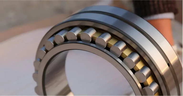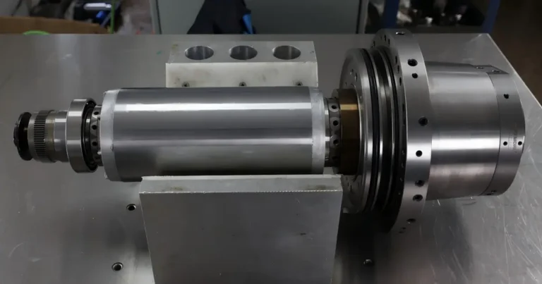

The angular contact bearing contact angle affects radial and axial load capacity, stiffness and speed capability. Two bearings can have the same bore, outside diameter and width but different contact angles, so fitting the same bearing seat does not guarantee the same performance.
A smaller contact angle generally favors radial load support and high-speed operation. A larger angle provides greater axial load capacity. The right choice depends on load, speed, preload and the bearing arrangement.
What Does Contact Angle Mean?
In an angular contact ball bearing, load passes between the inner and outer raceways through the balls along an inclined contact line. The contact angle is measured between that line and a plane perpendicular to the bearing axis.
A smaller angle directs more of the contact force radially. A larger angle directs more axially. This is the main reason contact angle affects the balance between radial and axial load capacity.
A single-row angular contact bearing supports axial load in one direction. An opposing bearing or bearing set is needed for axial support in the other direction.
The catalogue angle is nominal. The operating contact angle can change with load, preload and speed. It is not fixed under every running condition.
15° vs. 25° vs. 40°: Load and Speed Comparison
The comparison below assumes the same bearing dimensions, ball size, ball count and materials, with comparable raceway geometry and operating conditions. It isolates the general effect of changing the nominal contact angle.
| Contact Angle | Relative Radial Load Capacity | Relative Axial Load Capacity | Speed Tendency |
|---|---|---|---|
| 15° | Higher | Lower | Generally favors higher speed |
| 25° | Intermediate | Intermediate | A compromise between speed capability and axial support |
| 40° | Lower | Higher | Generally lower speed capability |
Higher and lower are relative within this comparison. They describe general directional load-capacity trends, not a numerical ranking of catalogue basic load ratings. Actual permissible loads and speeds must be checked using the manufacturer’s data.
These are not the only available angles. Some precision bearing ranges include 18°, 20° or 30° options. Availability depends on the manufacturer and bearing series.
15° Bearings: A Common Choice for High-Speed Spindles
A 15° contact angle is commonly used where speed is a major requirement and axial load is relatively moderate. High-speed milling and grinding spindles are typical examples.
Under otherwise comparable conditions, the smaller angle favors radial load capacity but provides less axial load capacity than a 25° or 40° design.
This does not mean every 15° bearing can run faster than every 25° bearing. Ball size, cage design, rolling element material, lubrication and preload can change the comparison substantially.
For machine tool spindle bearings, check the speed rating for the actual bearing set and lubrication method—not just the contact angle.
25° Bearings: A Balance Between Speed and Axial Support
A 25° bearing is often considered when a spindle needs more axial support while retaining useful speed capability.
Compared with an otherwise similar 15° design, it generally offers greater axial load capacity, with some reduction in radial load capacity. It may also provide higher axial stiffness under comparable loading and preload conditions.
This can be useful where cutting forces have a significant axial component. However, higher axial stiffness does not necessarily mean higher overall spindle rigidity. Radial stiffness, bearing spacing, shaft geometry and the support arrangement also affect tool-point deflection.
When selecting machine tool bearings, assess the complete support system rather than choosing an angle from the machine type alone.
40° Bearings: For Greater Axial Load Capacity
A 40° contact angle places greater emphasis on axial load support. Under otherwise comparable conditions, it generally offers higher axial load capacity and lower radial load capacity than 15° and 25° designs.
It can suit combined-load applications with substantial thrust, but it is not a default upgrade for a high-speed spindle. Changing from 15° or 25° to 40° can affect stiffness, heat generation and speed capability.
A larger contact angle also does not make a bearing more precise. Accuracy grade and contact angle are separate specifications.
Can You Replace One Contact Angle with Another?
Not on dimensions alone. A replacement with the same external dimensions but a different contact angle is a design change, not a straightforward interchange.
Before changing the angle, check:
- Radial and axial loads, including load direction.
- Maximum speed and continuous operating speed.
- Required axial, radial and moment stiffness.
- Bearing arrangement and matched-set requirements.
- Preload specification, fits and operating temperatures.
- Lubrication, cage design and rolling element material.
Keep the complete bearing designation, including all suffixes. Contact-angle codes are not universal across manufacturers. Changing one bearing within a matched set can compromise the intended preload and load sharing.
For machine tool bearing replacement, send the original markings, set arrangement and spindle operating conditions for review.
Choosing the Right Contact Angle
Start with the load and speed requirements:
- Consider 15° when high speed and radial load support are priorities, with moderate axial loads.
- Consider 25° when the design needs a compromise between speed and axial support.
- Consider 40° when axial load capacity takes priority and the bearing’s speed rating is suitable.
Then verify the specific bearing ratings, preload and arrangement. Contact angle narrows the choice; it does not complete the selection.