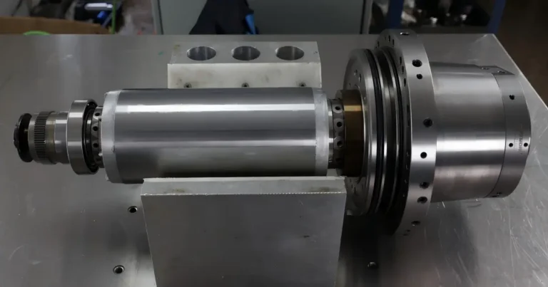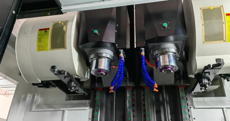
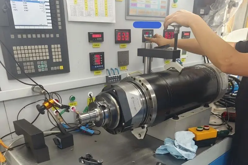
Spindle bearing run-in is a controlled initial operating procedure used after bearing replacement or a spindle rebuild. Before returning the machine to normal operation, it provides an opportunity to check temperature trends, vibration, noise and drive load.
A rebuilt spindle should not go straight from the assembly bench to full-speed cutting. Even when the replacement bearings match the original specification, the assembled spindle still needs to be checked under the prescribed test conditions. For grease-lubricated bearings, initial running also helps redistribute grease around the rolling elements.
The correct procedure depends on the spindle design, bearing arrangement and lubrication system. Follow the spindle manufacturer’s commissioning instructions and any applicable bearing or lubricant requirements. A generic speed-and-time schedule is not a substitute for those instructions.
Run-In and Commissioning Are Not Quite the Same Thing
The terms are often used together, but they describe different parts of the job.
Grease run-in concerns the redistribution of grease during initial operation. Grease near the rolling elements can create churning losses and heat until a more stable distribution develops. The result depends on the grease, fill quantity, bearing design and operating conditions.
Spindle commissioning is broader. It checks the assembled spindle, including its lubrication supply, cooling, drive, sensors and running behaviour. An oil-air-lubricated spindle does not undergo the same grease redistribution process, but it still needs controlled checks before normal operation.
Neither process corrects an unsuitable bearing, an incorrect fit or excessive preload. If an assembly problem is producing heat, continued running can make it worse.
What to Check Before the First Start
Before starting, review the assembly records and confirm that the checks described in the machine tool bearing replacement guide have been completed. Verify the complete bearing designations, arrangement, lubrication specification and required settings.
If a setting was changed during the rebuild, record the change and its technical basis before testing. Do not rely on the run-in process to establish whether an undocumented adjustment was correct.
Bearings, Retention and Rotation
Check that the bearing arrangement and orientation agree with the spindle drawing. Confirm that retaining parts, spacers and locking devices were installed and secured according to the specified procedure.
Where the spindle design permits a manual rotation check, follow the equipment instructions and isolate the drive first. Investigate binding, scraping or an unexpected change in resistance. A hand-rotation check alone cannot confirm that preload is correct.
The complete machine tool spindle bearing arrangement must be checked as a system. Correct individual bearings do not guarantee that the assembled support, retention and thermal expansion arrangements are correct.
Lubrication Supply
For grease lubrication, verify the specified grease and fill quantity. Adding more grease “for safety” can increase churning and temperature, especially at higher speeds. Do not add grease to a pre-greased bearing unless the applicable instructions require it.
For oil-air lubrication, check the specified oil, metering system, air supply and delivery lines. Verify that lubricant reaches the intended points using the system’s prescribed checking method. A pressure indication at the supply unit does not, by itself, prove that every bearing is receiving oil.
Grease and oil-air systems require different preparation and operating checks. Our guide to machine tool spindle bearing lubrication explains the main differences and the factors that affect lubricant selection and delivery.
Cooling and Test Configuration
Confirm that the cooling circuit is operating with the required fluid, flow and temperature settings. Keep those settings consistent during the test so that the temperature record remains useful.
Check the spindle’s required test configuration. Depending on the machine, this may include a specified toolholder, drawbar condition, spindle orientation or other equipment. “No cutting load” does not necessarily mean that the spindle should run without a toolholder.
Use the machine’s guards and approved controls. Do not bypass interlocks to carry out a run-in test.
How to Approach a Controlled Spindle Bearing Run-In
Prepare the test schedule before starting. It should identify the permitted speed stages, monitoring points, acceptance criteria and stop conditions. Use the manufacturer’s schedule where one is available.
If the original procedure is missing, obtain guidance from the spindle manufacturer or a qualified spindle service provider. Bearing catalogue speed limits alone are not enough to create a commissioning schedule: the assembled spindle also has limits associated with its drive, lubrication, cooling and attached equipment.
- Record the starting conditions. Note ambient temperature, initial sensor readings, cooling settings and lubrication status.
- Begin at the prescribed initial speed. Check for unexpected noise, vibration, drive load or lubrication alarms.
- Monitor the trend at each stage. Follow the specified hold periods and thermal criteria rather than increasing speed simply because the spindle has run for a few minutes.
- Increase speed only when the procedure allows it. Continue recording the same measurements at consistent intervals.
- Complete the specified final checks. Include any required cool-down, restart or repeated test sequence.
Some grease run-in procedures use interrupted operation or cooling periods. Others specify different sequences. Do not combine parts of unrelated procedures and assume the result will suit the spindle.
What to Monitor During Each Speed Stage
A single temperature reading tells you less than a record of how the spindle reached it. Record elapsed time and operating conditions alongside the measurements. Where a suitable pre-rebuild reference is available, compare readings taken under equivalent conditions.
| Item | What to Record | What It Helps You Check |
|---|---|---|
| Temperature | Readings at fixed sensor positions, ambient temperature and cooling conditions | Whether the thermal trend approaches the specified stable condition or continues to rise |
| Vibration | Speed, measuring position, direction, units and instrument settings | Changes between stages or against a suitable reference measurement |
| Noise | New scraping, knocking or other unusual sounds, with the speed and time of occurrence | Conditions that need investigation before further running |
| Drive load | Available current, torque or power readings at the specified test condition | Unexpected changes in resistance or drive behaviour |
| Lubrication and cooling | Supply status, relevant pressures or flow indications, settings and alarms | Whether supporting systems remain within their specified operating conditions |
Temperature: Use the Same Measurement Point
A housing surface reading is not the same as the bearing’s internal temperature. Sensor position, heat transfer through the housing and coolant operation all affect the reading.
Use the same measurement point and method throughout the test. If using an infrared instrument, account for surface emissivity and reflections; bare metal can give misleading readings. Take measurements using a safe, approved method without removing guards or approaching rotating parts.
An initial temperature rise may occur during grease redistribution, but it is not automatically acceptable. The important questions are whether the reading remains within the specified limits and whether its trend satisfies the procedure.
Vibration: Compare Like with Like
Keep the measuring location, direction and instrument settings consistent. Measurements taken with different frequency ranges or units should not be compared as if they were equivalent.
A rise in vibration at one speed does not prove bearing damage. Balance, the toolholder, the drive and structural resonance can also contribute. It does mean that the change needs to be understood before the spindle is accepted.
Drive Load: Supporting Evidence, Not a Preload Measurement
Drive current or torque can help identify a change in running resistance, but it is also affected by the motor, drive settings, speed and attached equipment.
Do not use current alone to set bearing preload. The required mechanical setting and checking method depend on the spindle design, as discussed in our guide to CNC spindle bearing preload.
When to Stop and Investigate
Use the stop criteria established for the spindle. If an alarm or abnormal condition occurs, stop according to the machine’s prescribed procedure. Isolate the equipment before carrying out an inspection.
Conditions requiring attention include:
- Temperature exceeding the specified limit or rising faster than the procedure permits.
- A new or substantial vibration increase.
- Scraping, knocking or another unexpected mechanical sound.
- Unexpected drive load, unstable speed or a drive alarm.
- Loss of lubrication delivery or cooling.
- Leakage, smoke or signs of mechanical contact.
Record the speed, elapsed time and readings immediately before the stop, where this can be done safely. That information is useful when separating a lubrication problem from an assembly, cooling or drive problem.
Repeatedly restarting a spindle to see whether the problem disappears is not a sound troubleshooting method. Review the evidence first. Our machine tool bearing failure analysis guide covers common symptoms and causes, but symptoms alone should not be treated as a confirmed diagnosis.
Common Run-In Mistakes
Going Straight to the Intended Production Speed
This leaves little opportunity to detect an abnormal trend at a lower speed. Use the approved sequence even if the spindle feels smooth during a brief initial check.
Using Extra Grease to Address Rising Temperature
Heat does not necessarily mean lubricant shortage. Excess grease, excessive preload, incorrect fits and inadequate cooling can all contribute. Establish the cause before changing the lubrication quantity.
Assuming Every Temperature Rise Will Settle
Grease redistribution can produce a changing thermal response. An assembly fault can also produce rising temperature. The distinction must come from the prescribed limits, trend and supporting measurements, not from an assumption that more running will solve it.
Accepting the Spindle Because It Sounds Quiet
Quiet operation is useful evidence, but it does not confirm running accuracy, thermal stability or correct preload. Complete the required measurements and acceptance checks.
What to Check Before Returning the Machine to Service
Completing the run-in schedule is one part of acceptance. Carry out the spindle manufacturer’s remaining commissioning checks, which may include runout at specified reference points, repeatability after warming, tool retention checks and controlled machining tests.
Where machining tests are required, use the approved conditions. A stable no-cutting-load run does not prove that the spindle will meet accuracy and temperature requirements under production loads.
Keep the final test record with the rebuild documentation. It should include:
- The complete bearing designations and assembly settings.
- Lubricant specification and grease quantity or oil-air system settings.
- The run-in procedure used and test configuration.
- Speed stages, elapsed times and measurement records.
- Any interruptions, alarms and corrective work.
- Final inspection results and acceptance criteria.
These records provide a reference for later checks. Without them, it is harder to decide whether a future temperature or vibration change is genuinely new.
A successful spindle bearing run-in is not simply a period of operation without an alarm. It is a documented check that the spindle meets the prescribed running criteria, followed by the remaining inspections required before release to service.
Frequently Asked Questions
How long should spindle bearing run-in take?
There is no universal duration. The required sequence depends on the spindle, bearings, lubricant and operating conditions. Follow the specified speed stages, hold periods and acceptance criteria rather than choosing a fixed running time.
What temperature is acceptable during run-in?
Use the limits specified for the spindle and its measurement points. A housing surface reading cannot be treated as the internal bearing temperature. Record the trend and cooling conditions as well as the temperature itself.
Do oil-air-lubricated spindle bearings need run-in?
They do not undergo the same grease redistribution process, but the rebuilt spindle still needs the prescribed commissioning checks. Verify lubricant delivery and monitor temperature, vibration and other required measurements before normal operation.
Can run-in correct excessive bearing preload?
No. Run-in is not a correction for an incorrect mechanical setting. If excessive preload is suspected, stop and review the assembly using the spindle’s specified checking procedure.